|
|
uSLAM (Hydraulic Transient Analysis) Windows Application uSLAM (Unified Steam Liquid HAMmer) uses the Method of Characteristics to solve fast hydraulic transient problems for design or diagnostic analysis in piping systems. In general, this computer application calculates the “Unsteady Flow” or “Fluid Transient” response in a piping system resulting in pressure, velocity, density, and speed of sound changes with time. In a liquid system, the pressure and flow “waves” propagate in the system when waterhammer occurs. The application can model cavity formation and collapse (traditional water column separation and collapse), filling of a voided system, valve actuation, pump actuation (start and trip), etc.. In addition to the calculated surge pressures and velocities, this program also calculates forces on pipe segment between to elbows using Moody’s methodology.
Key Features of uSLAM:
Extracted
from Paper # FEDSM99-6891, “DIAGNOSTIC EVALUATION OF A SEVERE WATER HAMMER EVENT IN THE FIRE PROTECTION SYSTEM OF A
NUCLEAR POWER PLANT”, Proceedings of the 3rd ASME/JSME Joint Fluids Engineering Conference July 18–23, 1999, San
Francisco, California. The
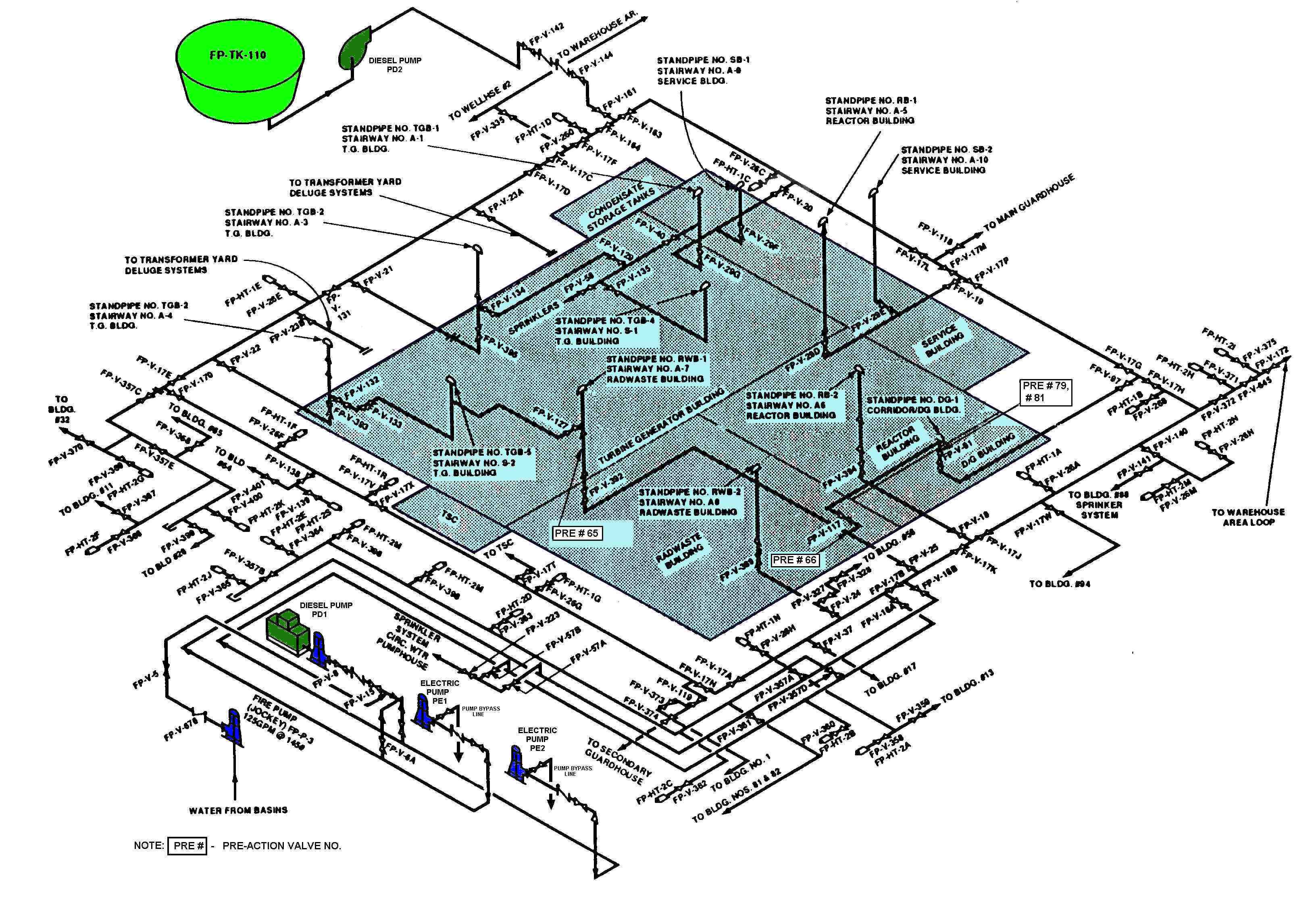
system has four main fire pumps and a keep full jockey pump. Figure 1 shows a schematic of the water subsystem. An underground
fire main yard loop provides water to the various plant areas. This fire main is normally maintained pressurized by a low
capacity (150 gpm) jockey pump to a pressure of 135 psig. When a demand for water is placed on the system, four standby fire
pumps start automatically in a sequence based on system pressure. These pumps consist of two electric-driven pumps (PE1 and
PE2) and one diesel driven pump (PD1), each with a capacity of 2000 gpm, taking suction from the circulating water basin.
The second diesel-driven pump (PD2) takes suction
from a separate tank and has a capacity of 2500 gpm. The discharges of the two electric pumps have 6-inch branch lines that
can bypass the flow back to the suction reservoir. These bypass lines have pressure modulation valves that keep the pump discharge
pressure at approximately 140 psig. When the system is in standby with the main electric pumps not running, these pressure
modulation valves are fully open. They are designed to bypass almost all the pump discharge flow to the suction reservoir
when fully open. These valves, therefore, play a significant role in controlling the flow from the electric pumps to the system
during the transient. The computer model described in Figure 1 above was
run for the cases of pre-action valve P66 actuating alone and also for the opening of valve P66
followed by P81 actuating 4 seconds later. As will be discussed later, the first case simulated
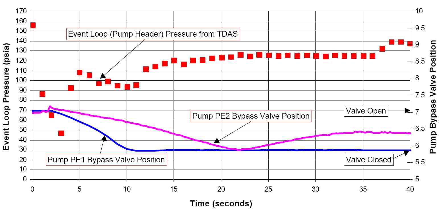
the conditions most likely to have existed during the water hammer event. Figure 4 shows the measured pressure trace at the
electric/diesel pump header taken from the TDAS for the event. It also shows the variation of the
pump bypass valves positions with time. The TDAS trace, in which data is sampled every second, does
not appear to exhibit any evidence of water hammer pressure surges. This was most probably due to
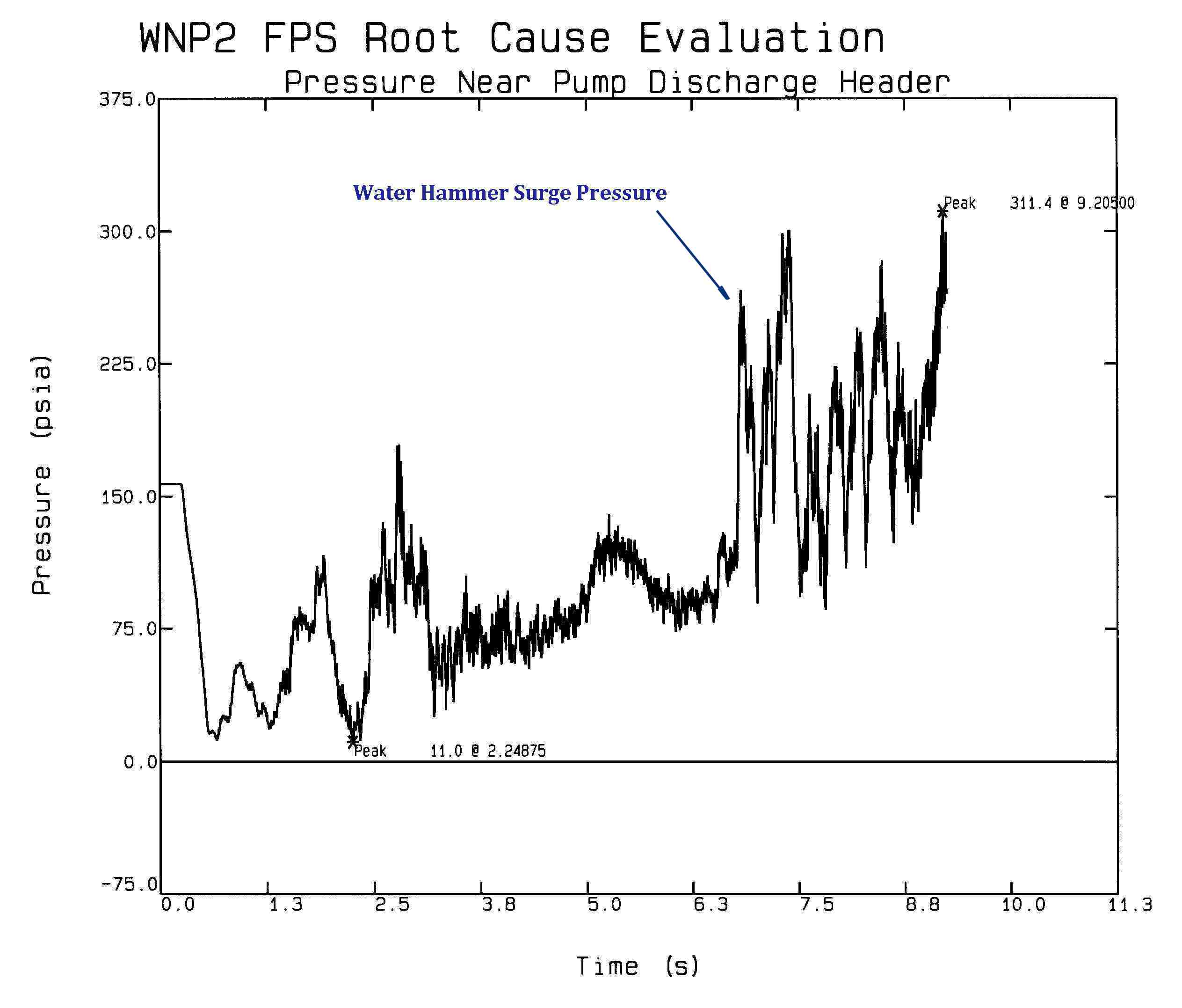
the data sample rate. The pressure plot near the TDAS measurement
location for the case of P66 actuation is shown in Figure 5 below. Comparing
the predictions to the measured trace in Figure 4 one can see that the agreement between the measured and predicted values
is very reasonable. Note that due to the slow sample rate, TDAS did not pick up the surge pressures.
|
|
|


